Annular Ring
A via is formed by drilling a hole through a pad on a PCB board. The annular ring refers to the area between the edge of the drill hole and the pad corresponding to the hole.
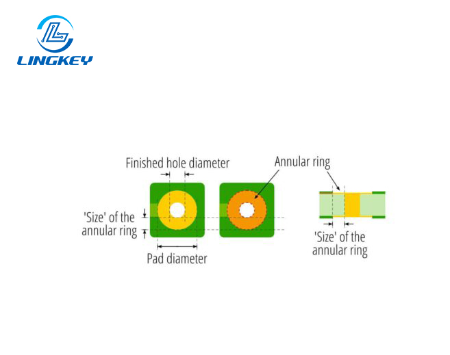
How do I calculate the annular ring size?
Mathematically, the annular ring width is equal to the difference between the pad diameter and the via diameter, divided by 2. For example, if the pad diameter is 24 mil and the via diameter is 12 mil, the annular ring width is [(24 – 12) / 2] = 6 mil.
The formula is as follows:Annular Ring = (Diameter of the Copper Pad – Diameter of the Via/Hole) / 2
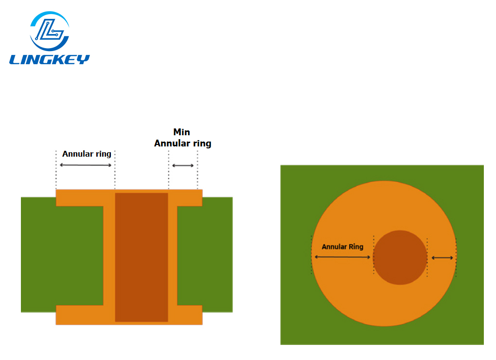
During PCB manufacturing, the width of the annular ring is very important. The ring should be wide enough, and the minimum width should be greater than or equal to the specified design width. If the ring width is too small, it may affect component soldering and may also cause pad breakage. This is related to the area of the circuit entering the pad, thus affecting the normal operation of the circuit.
Common Annular Ring Situations
During the drilling process, the drill bit may be affected by other factors, causing the drilling position to deviate from the center position and be subject to a certain tolerance. Therefore, the following three situations may occur after drilling.
- Good vias: A good via is located at the center of the pad or within the allowable deviation range, ensuring a good and stable electrical connection.
- Tangent: When the drill bit is misaligned with the marking point, the drilled via will be off-center. When one edge of the via is closer to the side of the pad, it will appear tangent.
- Breakthrough: When the via is too large and extends beyond the pad boundary, causing the pad to be partially cut or broken, it is a breakthrough.
Tolerances to Consider During Design
During the drilling process, the drill bit may deviate slightly due to other factors, typically within a ±0.05mm deviation range. Therefore, it is crucial to allow for a larger annular ring width during the design and production process to prevent excessive via deviation and resulting pad breakage.
Calculation example: Assuming a target minimum annular ring width of 0.10mm, a drilling deviation of ±0.05mm, and a hole diameter of 0.30mm, the pad diameter = 0.30 + 2 × (0.10 + 0.05) = 0.60mm.
This ensures that even with hole deviation, the annular ring width remains at 0.10mm, ensuring reliable electrical connections.
