Flex PCB: Flex PCB design and Manufacturing
Table of Contents
ToggleIntroduction to Flex PCB Prototyping
In the main of modern electronics, the need for miniaturized, reliable, and flexible circuit design is the driving force behind innovation. Rigid PCBs alone too often fall short of fulfilling these requirements, particularly for products such as wearables, leading-edge medical devices, and dynamic applications including robotics and foldable devices. Flex PCB prototyping appears as a critical enabler to lead the way for inventive circuit board design and fast design turn around in electronic engineering.
A flex circuit board— and its higher-end variant, the rigid-flex board— brings together the mechanical properties, flexibility, and electrical capabilities of a engineered substrate in a flexible form. Using layers of polyimide as the base material and incorporating conductive copper lines, these boards fit almost any shape, freeing the need for bulkier wire harnesses. This means that the circuit design and assembly is hugely simplified.
Although flex PCB prototyping appears to be a simple process on paper, it is a balancing act between the design intent and manufacturing capabilities. At LingKey, Engineering Teams routinely support early stage flex/rigid-flex prototypes via DFM reviews in helping designers find the right balance of flexibility, reliability, and manufacturability prior to product tool production.
Understanding Flex PCBs: Structure, Materials, and Key Benefits
What is a Flexible Printed Circuit Board and Why Are They Essential?
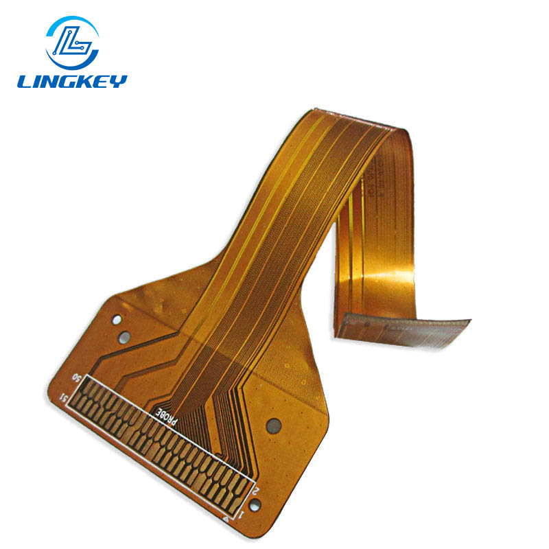
flex circuit board—also known as Flex PCB or flexible circuit—is a multilayer PCB with flexible insulating materials as a base material instead of rigid materials such as FR4. Unlike conventional rigid PCBs, these circuits can be bent and folded, making them suitable for dynamic uses where motion or limited space is involved. Flex circuits are particularly beneficial in products such as wearable technology, automotive dashboards, aerospace wiring and medical devices where flexibility, reliability and small size is critical.
Structure and Materials
The main elements of flex designs include:
- Base Material: Polyimide films (0.2mm or 5mm thick) providing flexibility, dielectric insulation and high thermal stability.
- Conductive Layers: Copper layers are used to form conductive tracks that, in multilayer flex constructions, are stacked and connected by plated vias.
- Adhesives and Coverlays:Coverlays are used for bonding and protection; the coverlay materials protect the conductors and allow for mechanical flexibility in the flex.
- Stiffeners: it was applied to areas that required reinforcement during pcb assembly, which is typically rigid fr-4 or stainless steel.
- Surface Finish Solutions: ENIG or HASL to achieve good solder joint reliability and long life even in dynamic or medical application.
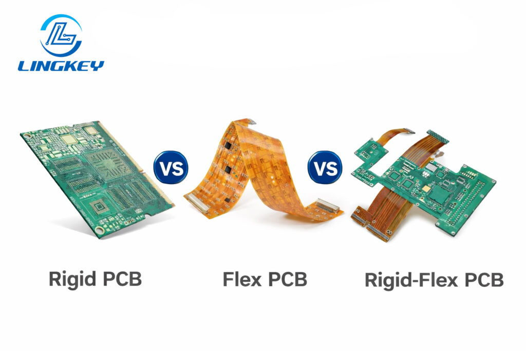
Rigid vs. Flex and Rigid-Flex PCBs
Feature | Standard Rigid | Flex Boards | Rigid-Flex Boards |
Min. Thickness | ~0.5mm | ~0.2mm | 0.2–1.0mm |
Bending/Flexibility | None | Dynamic/static | Selective regions |
Material | FR-4 | Polyimide | FR-4 + Polyimide |
Typical Applications | Static, flat | Wearables, sensors | Complex 3D design |
Solder Joint Reliability | High if fixed | Challenging in flex | Highest for rigid/flex-joint |
Weight/Space Optimization | Moderate | High | Highest |
Wire Harness Replacement | No | Yes | Yes |
Add Your Heading Text Here
- Space and Weight Savings: Flex boards can be bent or folded to fit into small spaces, significantly minimizing the device footprint.
- Mechanical Adaptability: In particular, in dynamic applications, boards can be flexed and twisted repeatedly – a necessity in wearable technology and robotics.
- Signal Integrity: Brief, straight traces ease EMI control and improve electrical performances.
- Simplify Assembly: Assembly reliability and manufacturability are improved by removing bulky wire harnesses and connectors.
- Flex and Rigid-Flex Capabilities: Rigid and flexible layers can be combined for optimum configuration and strength.
Typical Applications of Flex PCB Prototypes
Flexible PCB prototypes and rigid-flex boards are the building blocks for varying products and industries including:
- Consumer Electronics: From smart phones and foldable displays to compact cameras, flex circuits make interconnections easier and reduce volume dramatically.
- Automotive Industry: Suitable for dashboards, control panels, sensors and lighting applications where space and reliability considerations demand robust and flexible designs.
- Medical Equipment: As medical devices become smaller, flex and rigid-flex PCBs are now selected for diagnostic sensors, imaging instruments, and next-generation wearables that require a board thickness of just 0.2mm in the flex area.
- Aerospace Applications:Is crucial in satellites, drones, and avionics, where each gram of weight matters in these and environmental reliability must be.
- Industrial Devices: Robotics and IoT sensors use flex circuits for intricate routing and to withstand repeated motion profiles.
Types and Construction of Flexible PCB Prototypes
Types of Flex Circuits and Rigid-Flex Boards
Understanding the range of flexible PCB offerings is crucial for optimal product design:
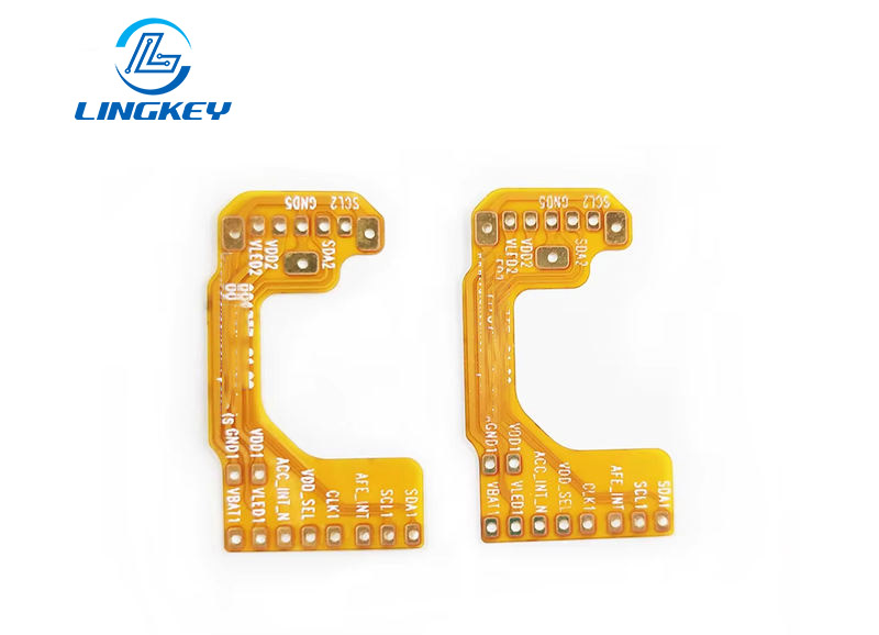
- Single-Sided Flex Circuit Board: One copper layer in the circuit, maximum flexibility, and cost effective for the simple interconnects.
- Double-Sided Flex Circuits: Two copper layers, vias providing additional routing resources and flexibility.
- Multilayer Flex Circuits: Several flex layers separated by dielectric polyimide films, allowing multi-level configuration and high circuit density.
- Rigid-Flex Boards: Rigid-flex integration ideal for complex 3D constructs requiring both rigid support and flex adaptability—reduces solder joint strain and enhances overall reliability.
Surface Finish and Stack-Up Considerations
Choosing appropriate materials and stack-up is vital for performance:
- Surface Finishes: ENIG is preferred for fine pitch assembly and long term reliability, and OSP or HASL can be selected if youre only making a simple prototype.
- Stack-Up Design: Make sure you know exactly where rigid and flex layers are required, and match the mechanical strength of the rigid boards with the flexibility of the flex circuits.
Flex PCB Design Guidelines: Best Practices from Concept to Prototype
Designing Flex PCBs - Critical Set of Design Rules
Flex and rigid-flex designs only work properly when strict circuit board design rules are followed:
- Bend Radius: The copper traces must be perpendicular to the bend and not directly over a 90 degree fold. For a bend radius of 2mm for 0.2mm thick flex.
- Component Placement: Avoid placing heavy or heat-sensitive electronic components in areas expected to flex.
- Trace Configuration: Use rounded instead of angled traces in bending areas. Keep your trace width adequate, say 0.5mm on power lines, and don’t make sudden changes from flex to rigid areas.
- Via and Pad Design: Avoid via-in-pad on flex layers. Strengthen solder joints and do not expose copper unless sealed with coverlay.
- Mechanical Strength: Add stiffeners to connector areas or areas that are subjected to mechanical load during pcba.
- Dynamic Applications: For repeated flexing, use annealed copper and keep conductor runs as wide as design rules permit.
- Minimize Layer Count: Reduce the flex layers in dynamic areas when possible to enhance
Design and Layout Tools
Use professional tools for flexible circuit board and rigid-flex design:
- Material Selection Engines: Assistance in specifying the right polyimide and adhesive system for the end use is provided.
- PCB Design Tools: Altium, Eagle and KiCAD also provide flex and rigid-flex features for accurate design and layout.
- DFM Review: Always talk to your PCB assembly partner for manufacturability checks prior to ordering prototypes.
The Flex PCB Prototyping Process: Manufacturing Techniques & Workflow
The production of flex circuits involves unique processes that are different from the standard rigid PCBs. Knowledge of each process step is needed for proper design, assembly confidence, and troubleshooting.Here’s a look at how today’s flex circuits go from digital design to physical prototypes:
Material Selection & Lamination
The process begins with the substrate – usually polyimide – which is heat resistant and flexible. In the case of hybrid rigid and flexible or rigid-flex, one or more rigid layers is added to strengthen sections that need mechanical strength, such as connector mounting points.
- Dielectric layers: Conductive layers are insulated with polyimide, the thickness of which is selected determined by the required flexibility (from 0.2 mm for wearable technology to 0.5 mm or more for medical equipment).
- Copper foil: Electrodeposited or rolled copper provides conductive pathways.
- Adhesives: For use in securing flexible and rigid portions, it shall conform to the same thermal cycling
Circuit Patterning and Etching
The circuit pattern is imaged on the copper using photoresist and UV exposure, then etched away to remove the unwanted copper-defining high density traces and flex layers. This allows design innovation, resulting in much smaller, more complex circuits than on traditional rigid PCBs.
Drilling, Plating, and Via Formation
- Laser or mechanical drilling made holes for vias, which electronically connected stacked flex layers or rigid and flex layers.
- Copper platingensures electrical continuity.
Coverlay Application and Solder Resist
Coverlay films (usually of polyimide) protect the exposed copper for enhanced durability, reliability and flex-life. In surface-mount assemblies, selective coverlay windows are opened only where components are to be soldered — a prerequisite for successful PCB assembly.
Rigid Section and Stiffener Bonding (Rigid-Flex Construction)
With rigid-flex circuit boards, the rigid and flex components are laminated together. Rigid-flex interfaces: the board house engineers are told where the rigid and flex portions meet and a series of design rules are applied to ensure the layout fulfills the intent of folding/bending without compromising the mechanical or electrical performance.
Surface Finish Solutions & Assembly Preparation
Surface finish (ENIG, OSP, HASL, etc.) is applied to exposed pads — this is essential for a reliable solder joint, particularly in applications such as medical devices where solderability and life are so important.
Placement of components is also very important in the assembly. Never place sensitive or large parts directly on a flex area – place them on rigid areas or reinforce flex areas with an appropriate stiffener.
Profiling and Final Inspection
Boards are routed to final shape (using laser or die cutting for flex circuits) and inspected in full.Every prototype undergoes:
- Electrical testing(for shorts/opens and impedance control)
- Microsection analysis(inspecting internal stack-up quality and via reliability)
- Dynamic bending tests for applications in which the product is subjected to bending, as in wearable technology or foldable consumer products.
Cost Factors, Scalability, and Environmental Sustainability
Cost Factors in Flex PCB Prototyping
Factor | Impact on Cost |
Number of Flex Layers | More layers increase cost |
Use of Rigid-Flex Configuration | Adds manufacturing complexity |
Thickness of Rigid and Flex Areas | Ultra-thin (0.2mm/0.5mm) can cost more |
Type of Surface Finish (e.g., ENIG) | Some, like hard gold, more expensive |
Volume and Turn Time | Prototypes have higher unit costs |
Design Complexity | Tighter tolerances and smaller vias increase price |
Environmental Sustainability of Flex Circuits
- Material reduction: Flex circuits require less base material than standard rigid boards, reducing waste.
- Recyclability: Polyimide films and copper are frequently recoverable. Whenever possible, select lead-free finishes to improve recyclability.
- Wire harness elimination: The use of rigid and flexible PCB assemblies in place of traditional wire harnesses decreases the total amount of materials and facilitates end-of-life recycling.
Testing, Inspection & Quality Standards
Rigorous testing and inspection ensure reliability, particularly for products used in medical, automotive, or aerospace applications.
- Electrical performance: AOI, flying probe, and impedance tests verify signal integrity and detect shorts and opens.
- Mechanical strength: Flex circuits intended for dynamic applications are subjected to cycle bending tests (dynamic applications), at times the flex is to thousands or millions of cycles.
- Microsection analysis: Particularly for 0.2mm or thinner flex layers to check lamination and plating
- Compliance: Make sure your boards comply with the IPC standards for flex circuits or rigid-flex boards—crucial for purchasing in regulated industries.
Choosing a Flex PCB Prototyping Partner
Choosing a Flex PCB Prototyping Partner
Choosing the right flex PCB prototyping partner is not simply a sourcing decision—it has a ripple effect on design iter ation speed, prototype reliability, and downstream production success. Flex and rigid-flex circuits add mechanical, material, and process variables that require more than your typical PCB fabricator.
When evaluating a flex PCB prototyping partner, look for:
- Proven Flex & Rigid-Flex Engineering Experience
The vendor must be able to show real-world know-how with polyimide materials, bend-radius control, rigid–flex transitions, and dynamic flex-life aspects over actual applications.
- Strong DFM and Early Engineering Involvement
Early-stage DFM review is necessary to uncover potential risks including copper balance, coverlay design, stiffener placement, etc. and assembly limitations prior to prototype building.
- In-House Manufacturing and Testing Capabilities
Full process control including lamination, drilling, electrical testing and microsectioning contributes to uniformity, rapid feedback and less design cycles.
- Clear Communication from Prototype to Production
A strong partner will be able to support quick-turn prototypes, but will also offer advice and assistance that will make for a seamless transition into the low- and medium-volume manufacturing.
LingKey offers flex PCB prototyping with dedicated engineering support from early design review to prototype validation. With DFM-led advice, tightly controlled flex manufacturing and application-based testing, LingKey enables development teams to minimize re-spins, control cost and go confidently from concept to production-ready designs.
FAQs: Flex PCB Prototyping
How thin can a flex circuit board be?
Can rigid and flex layers be combined in a single configuration?
What are the design limits for dynamic applications?
Are flex PCBs sustainable?
Should I place components on the flex area?
Conclusion and Future Outlook
Flex PCB prototyping is important for any company that is advancing modern electronics. These boards streamline assembly, enhance reliability in both dynamic and static applications and enable design innovation to power the next generation of products that are evolving from medical equipment and automotive dashboards to the emergence of wearable technology. Prioritize education, adhere to a strong set of design rules, and consult with experts on flex and rigid-flex for best results.
")
")


")
")
")


