PCB Connector Types: Guide for PCB Design
Electrical connectors are central to every printed circuit board (PCB) and determine the manner in which signals, data and power are transmitted and received in all types of electronics. The realm of PCB connectors is very large and complex with almost millions of types and versions, each important to have stable and effective designing, manufacturing and working. Whether it’s robust board-to-board connections or a custom waterproof connector for extreme environments, the right connector makes a difference and choosing it is critical for every electrical engineer and designer.
Table of Contents
ToggleIntroduction
The selection of electrical connectors has a direct impact on product/system reliability, safety, and the harmonious operation of every circuit board. Connectors are employed to joins two or more PCB boards, which allows modular design and flexible manufacturing. These vital products are used in all industries from automotive electrical connectors & usb-c solutions to servers, medical devices, and industrial automation.
In the following guide to types of PCB connectors, you’ll learn everything you need to know about connectors — how they are used, how to select the right one, and design for best practice to ensure a reliable assembly.
Why Choosing the Right PCB Connector Matters
Selecting the correct connector is not just a mechanical consideration—it is one of the most critical design choices for an electrical engineer :
- Signal Integrity:All connectors must be visually accessible and lossless for analog and digital signals, in particular on fast digital buses.
- Power Delivery:Choose the connectors with appropriate current and voltage ratings to prevent thermal runaway and signal attenuation.
- Mechanical Durability:Mechanical strain, vibration, and thermal cycling may cause inferior connectors to become loose or deteriorate.
- Cost vs. Performance:There is always a trade-off. Select connectors that are a good balance between cost and the electrical and physical requirements.
Importance of Electrical Connectors in PCBs
Electrical connectors serve to join systems, allow modularity, facilitate serviceability, and ease testing and manufacturing. In complex products, particularly those with multi-board architectures, PCB connectors exist in different forms to enable plug and play upgrades, maintenance, or rapid field repairs.
Key Benefits:
- Modular Design:Swap or upgrade individual boards without full system replacements.
- Efficient Manufacturing:Simplifies assembly by allowing independent testing and rapid system integration.
- System Expansion:Common PCB connectors enable adding features via daughtercards, expansion modules, or external devices.
How Connector Selection Impacts PCB Layout and Assembly
Connector selection influences every stage of PCB assembly and layout:
- Footprint and Space:Circuit board connector types come in various shapes and pitch sizes, affecting available board space.
- Trace Routing:High-speed connectors may implement differential pairs or impedance-controlled traces to prevent signal integrity loss.
- Signal Quality and EMI:Careful placement and the right type prevent EMI (Electromagnetic Interference) and cross-talk between signals.
- Thermal Management: High-current connectors and power connectors require extra copper, larger pads, and specific land patterns to dissipate heat.
Types of Electrical Connectors Used in PCB Design
Knowing all the kinds of PCB connectors helps you design and diagnose with confidence. Each group is designed to meet specific application and electrical needs
Board-to-Board Connectors
Board-to-board connectors connect two circuit boards directly and are typically found in stacked or parallel PCB arrangements. They are also very popular in modular or small consumer electronics applications. Types include:
- Mezzanine connectors
- Coplanar connectors
- Right-angle connectors
Typical Uses: Embedded controllers, telecom, stackable IoT systems
Feature: High-speed data transfer rates with low signal loss.
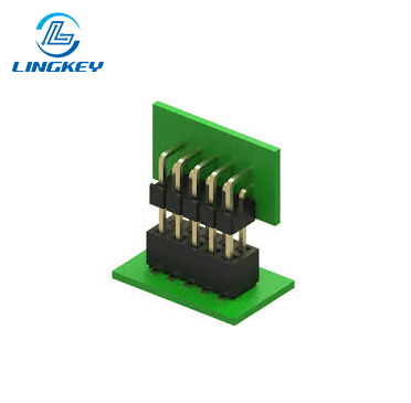
Wire-to-Board Connectors
The wire-to-board connectors found in today’s marketplace is the best solution for connecting wires to a PCB in consumer devices, industrial machines, sensors, and more.
Examples:
- Pin headers
- Socket connectors
- Terminal blocks
Feature: Secure locking mechanisms to ensure reliable and efficient power and signal transmission.
Board-to-Wire Connectors
These connectors are tailored for rapid assembly typically with pre-crimped wires and with latching or press-fit mechanisms. Applications: Automotive wiring looms and consumer appliances due to their strong mating cycles.
Edge Connectors
Edge connector (or card edge connector) can be mated with the edge of the circuit board connector, which is popular in memory modules, PCIe cards and plug-in expansion modules.
Backplane Connectors
Backplane connectors are used for centralized switching and high-density communications and are critical in servers, networking gear and storage appliances. Input/output (I/O) Connectors
Input/Output (I/O) Connectors
The I/O connectors comprise USB-C, RJ45 Ethernet, HDMI, and a few other connections on the outside. Engineering Consideration: Should support mechanical robustness and may require EMI shielding.
RF and Coaxial Connectors
Critical for RF circuits and high-speed data paths. Types: SMA, BNC, MCX Features: Shielding, impedance matching, low loss.
Power Connectors
Heavy-duty connectors are designed for large currents, usually greater than 10A, and a safety latch or a screw terminal is provided Applications: Industrial Controls, Robotics, Large Appliances.
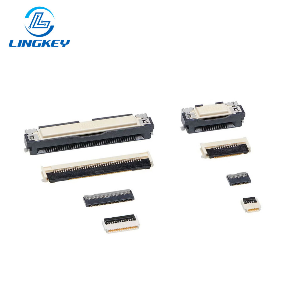
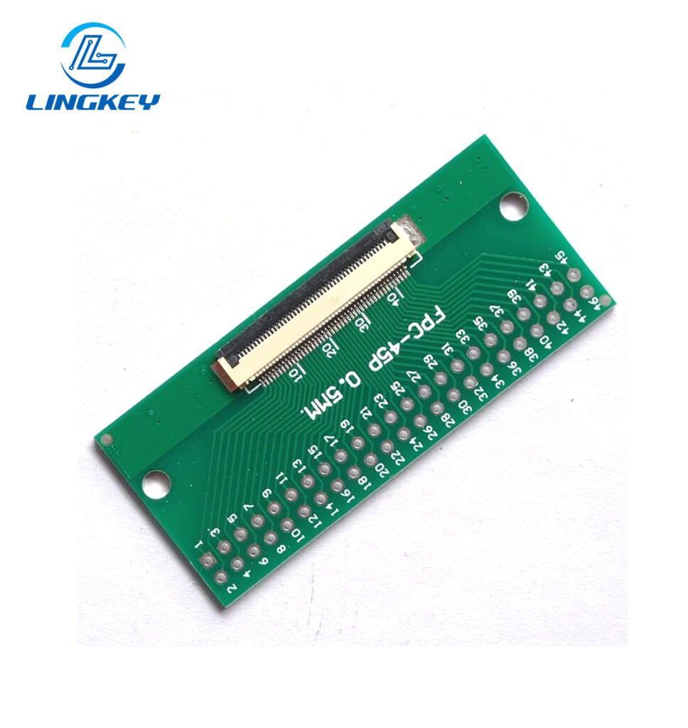
FPC/FFC Connectors
Flexible PCB connectors (FPC/FFC) are used for connecting soft, flexible cables—ideal for wearables, foldable devices, and when space is limited.
Circular, Modular, Micro/Nano Connectors
From rugged M12 circular connectors for industrial applications to ultra small solutions for medical or hearing aids, these connectors are offered in different pitch sizes and configurations and are ruggedized for extreme environments.
Detailed Comparison of PCB Connector Types
Connector Type | Used To Connect | Key Features | Mechanical Durability | Typical Applications |
Board-to-Board | Connect two PCBs | High-speed, modular | High | Embedded, telecom, custom PCB |
Wire-to-Board | Wires to PCB | Locking, field-service | Medium-High | Automotive, consumer electronics |
Board-to-Wire | Board to external wires | Quick assembly, robust | High | White goods, industrial |
Edge (Card Edge) | Edge PCB to socket | Pluggable, quick swap | Medium | Expansion cards, RAM, PCIe |
Backplane | Many signals to backplane | High-density, robust | High | Servers, routers, storage |
Input/Output (I/O) | External interfaces | Standardized, shielded | Medium | USB-C, HDMI, Ethernet |
RF and Coaxial | High-freq. signals | Shielding, impedance | High | Wireless, RF modules |
Power | Power supply lines | High-current, safe | Very High | Robotics, automation, IoT |
FPC/FFC | Flat/flexible cables | Compact, flexible | Low | Wearables, foldables |
Circular/Modular/Nano | Miniaturized or harsh | Rugged, sealed | High | Medical, industrial |
Special Considerations for Signal and Power
Signal Integrity
Maintaining signal quality is crucial in modern designs, especially for high-speed data. The following aspects are vital:
- Impedance Matching:Use the connectors with matched impedance to avoid signal reflection and signal loss, which is important for USB-C, HDMI and other high speed features. Impedance matched connectors also reduce the chance of data errors and communication problems, particularly when dealing with high speed digital buses such as those used in networking, storage and entertainment applications.
- Low Crosstalk and EMI:Choose connectors with a shielded construction or an integrated ground pin to reduce electromagnetic interference (EMI) and low crosstalk with adjacent high-speed signal lines. A good quality connector is required for high reliable operation in high noise environment or in a unit where many sensitive circuit are closely packed.
- Signal Loss:The very short signal path, the gold plated contacts and the robust enclosure ensure a perfect signal integrity. Signal loss can lead to corrupt data or device failure, and proteciton from that signal loss varies with type of electrical connector.
- Practical Help:For critical designs, electrical engineers will often perform simulation using tools prior to committing to a connector layout. Simulations help to confirm signal quality, to identify potential problematic areas for EMI, and to verify that the selected connector can support the required data transfer rates.
High-Current Connectors
High-current connectors are crucial when the delivery of power is a key function, as with industrial controllers, robots, or automotive electrical connectors:
- Contact Material:Choose gold or tin-plated contacts for low resistance and resistance to oxidation.
- Thermal Management:Look for power connectors with features to dissipate generated heat efficiently; robust thermal management helps prevent catastrophic failures like melting or thermal runaway.
- Current Rating:Always ensure the connector can handle your anticipated maximum current flow or you risk premature failure or electrical hazards.
Waterproof Connectors
In harsh environments, like marine, automotive or outdoor industrial, waterproof connectors are critical in providing protection against corrosion, short circuits and subsequent system or equipment failure:
- IP Ratings:Look for ratings like IP67 (protection against immersion in water up to 1 meter) or IP68 (extended immersion or submersion).
- Sealing Mechanisms:O-rings, rubber gaskets, and overmolded bodies are common sealing techniques. These prevent moisture ingress and maintain longevity.
- Use Case: A dockside industrial sensor system utilizes sealed connectors with IP68 rating and rubber gaskets to prevent water and dust from interrupting signal and power transfer, ensuring years of maintenance-free operation.
PCB Connector Mounting Techniques
How a connector is mounted to the circuit board influences its electrical performance, reliability and the environments in which it can be manufactured and operated.Mounting techniques include:
- Through-Hole Mounting:Traditional and still widely used for connectors that need strong mechanical attachment, such as heavy power or plug connectors. Through-hole components excel in environments prone to vibration and physical abuse.
- Surface-Mount Technology (SMT):Preferred for modern high-density boards. SMT connectors are placed automatically, allowing space savings and supporting automated optical inspection (AOI) and in-circuit testing (ICT).
- Press-Fit Mounting:No soldering required; instead, pins fit tightly into plated through-holes. Excellent for backplane connectors and high-reliability modular designs.
- Hybrid Mounting: Combines SMT and through-hole for improved stability and electrical performance. Hybrid solutions are particularly popular in automotive PCBs.
Key Factors to Consider When Selecting Connectors
Choosing the correct electrical connector is a matter of more than just matching up physical pinouts. Key design considerations are: :
- Environmental Conditions:Select connectors rated for the operational temperature, humidity, vibration, or potential exposure to chemicals and dust.
- Mating Cycles:Each connector is rated for a specific number of connect/disconnect actions. For field-serviceable products, opt for connectors with high mating cycle ratings.
- Cost vs. Performance:Weigh the performance you need against your budget. For non-critical paths, less expensive connectors may suffice; for vital systems, invest in engineered solutions.
- Manufacturer Support:Leading PCB connector brands provide comprehensive datasheets, detailed 3D models, simulation data, and excellent technical support to help with custom PCB design.
- Pitch Size & Form Factor:Ensure the connector fits your board’s available space without interfering with adjacent components or traces.
- Current and Voltage Ratings:Never underspec—always choose a connector designed to exceed your expected load under all conditions.
Connector Selection and Assembly Process
Connector choice tightly integrates with PCB design and manufacturing:
- Footprint Matching:Ensure your EDA library (Altium, Eagle, KiCAD) contains verified footprints for each connector.
- Assembly Considerations:Automated assembly, AOI, and ICT compatibility save costs and catch defects early.
- Testing and Quality Assurance:Post-assembly, use continuity tests, visual inspection, and even X-ray for complex or high-pin-count connectors.
- Troubleshooting: What are the most common failure modes? Not aligned properly, not enough solder or dirt. Choose connectors that have self aligning characteristics or tactile/visual indication.
Frequently Asked Questions
How do I choose between various mounting techniques for my PCB connectors?
Are waterproof connectors necessary for all outdoor applications?
Why are connector pitch sizes important?
Conclusion: Making the Right Choice
Selecting the right connector is not just checking a box on your BOM. It’s about signal integrity, mechanical durability and future-proofing performance. Consider this guide to be a foundation for PCB connector types — when you are reviewing your options, make sure you are evaluating each design, environment, and operational requirement before selecting the final one.
Remember: Even the best circuit board design can be compromised by an incorrect connector. But with the knowledge, simulation and professional advice of LingKey your trusted pcb manufacturer, the connector you choose will be a stepping stone to solid and efficient product success.
Connector Type | Mounting Techniques | Key Design Considerations | Primary Use Cases |
Board-to-Board | SMT, Through-Hole, Hybrid | Data rates, EMI, pitch | Stackable PCBs, LSI |
Wire-to-Board | Through-Hole, SMT | Mechanical strength, lock | Power, signal |
Edge (Card Edge) | Slot, press fit | Signal integrity | PCIe, RAM, expansion |
Backplane | Press-fit, SMT | High pin count, modularity | Servers, networking |
I/O Connectors | Through-hole, hybrid | Shielding, durability | USB-C, HDMI, Ethernet |
Power Connectors | Through-hole, hybrid | Current rating, thermal | Motors, IoT, control |
FPC/FFC | SMT | Flexibility, density | Foldables, wearables |
RF & Coaxial | Slot, SMT, through-hole | Impedance matching | Wireless, automotive |
Circular/Modular | Through-hole, hybrid | IP rating, sealing | Harsh environments |
")
")


")
")
")


