PTFE PCBs and Teflon: Guide to High-Frequency Performance
Table of Contents
ToggleIntroduction
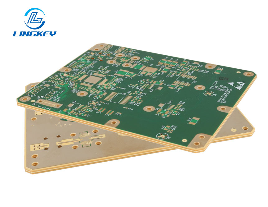
In the fast-changing application field of electronics, the substrate materials for high frequency circuit boards must be high-quality. A well known one is PTFE (polytetrafluoroethylene), known more commonly under the DuPont Teflon name. Its usage in the production of PCB boards, especially for RF and microwave modules, has revolutionized the industry since the discovery of PTFE.
Special characteristics of PTFE such as low dielectric constant, low dielectric loss, high thermal and chemical resistances and its insensitivity to changes in its operating conditions enable this material to offer uniqueness in electrical performance which can be applied in high end electronics, rapid pcb prototyping and pcb fabrication.
What is PTFE (Polytetrafluoroethylene)?
History and Chemistry of PTFE
In 1938, Dr. Roy Plunkett made a revolutionary discovery when he created PTFE. PTFE’s non-polar and chemically inert molecular structure played an important role in the development of electrical and electronic insulation products. The resin, PTFE, consists of tetrafluoroethylene repeating units which make it a highly stable fluorinated polymer, resistant to many chemicals and hydrophobic (water-repellent). As a result, PTFE became one of the most important types of insulating material on high-frequency printed circuit boards (PCBs) and Teflon®-based boards.
Forms and Manufacturing Processes
PTFE is available as:
- Granular resinfor molding sheets and rods
- Fine powderfor wire insulation and specialty laminates
- Aqueous dispersionfor coatings and impregnation
PTFE filled materials and ptfe Laminates can be produced with various resin blends, including glass or carbon or others, to increase the physical properties while reducing the overall cost. The combination of PTFE laminates in PCB manufacturing and fabrication provides extraordinary electrical characteristics, and laminates have superior physical stability.
PTFE Melting Point and Thermal Properties
The melting temperature of PTFE is approximately 327°C, however it does not actually flow as most other thermoplastics do. In fact, it forms a thick, viscous gel. This enables the PTFE-based PCB substrate material to tolerate high temperatures up to 260°C, and protect the high-sensitive application of high frequency and microwaves thermally.
What is Teflon? PTFE vs Teflon Explained
Teflon is the name given by DuPont (now Chemours) to that company’s brand of PTFE. Although Teflon PCBs and PTFE PCBs are essentially identical in all respects except for their brand name and source of manufacture, when choosing which to use for your printed circuit board design, it is important that you check that the actual material used in making the PCB and the electrical performance specifications of each are identical.
Why Dielectric Constant Matters in PCB Board Fabrication
A Printed Circuit Board (PCB) substrate’s Dielectric Constant (Dk) will determine the amount of electric charge that the substrate can hold. Lower Dk values along with lower Tangent Values (Loss Tangent), means signal propagation is slowed down less by the substrate, which is very important in High Frequency applications. Thus, PTFE and Teflon substrates with their low Dk make them suitable for use in High Frequency/Microwave Applications; where FR4 Substrates cannot be used due to their larger Dk values.
Material | Dielectric Constant | Loss Tangent | Typical Applications |
PTFE | ~2.02 | 0.0002 | RF, Microwave, High-Frequency |
FR4 | ~4.3 – 4.8 | 0.02 | Digital, General Electronics |
Rogers4350 | ~3.5 | 0.0037 | High Speed Digital/RF |
Ceramic | ~9–11 | <0.001 | Power Electronics, RF |
PTFE/Teflon Dielectric Constant: Characteristics, Loss Tangents, and Comparison
PTFE’s combination of extremely low dielectric loss and low dielectric constant qualifies PTFE as one of the finest materials for use in high-frequency or microwave applications. Designers of products that operate at these frequencies should evaluate PTFE with great interest because of its unique combination of attributes.
PTFE Dielectric Constant Table
Property | PTFE Value | FR4 Value |
Dielectric constant of PTFE | 2.0 – 2.1 | 4.2 – 4.8 |
Dielectric loss (tan δ) | 0.0002 (very low) | 0.02 (higher) |
Volume resistivity | 10¹⁸ Ω·cm | 10¹⁴ Ω·cm |
Service temp. | –268°C to 260°C | –50°C to 130°C |
Mechanical strength | Moderate | Good |
Key Characteristics:
- PTFE offersa stable dielectric constant from DC to microwave frequencies, meaning that signal transmission is reliable across variable conditions.
- The material is chemically inertand retains its electrical properties even after prolonged exposure to harsh environments.
- Due to the low dielectric constant and low loss, PTFE boards are the material of choice for RF and microwave applications.
Properties in Context
- PTFE has low surface energy—which complicates bonding (but is excellent for moisture resistance and durability).
- The low coefficient of frictionmakes PTFE surfaces ideal for moving components or flexible PCB manufacturing.
- Dielectric loss is extremely low, preserving signal clarity even at GHz-scale frequencies.
Advantages of PTFE/Teflon PCBs and Laminates in Electronics Manufacturing
Teflon/ PTFE circuit boards offer several advantages especially when used for high-end applications:
- Constant and small loss tangents:Maintain high signal integrity for high-frequency signal paths.
- Stable dielectric constant:Essential for impedance control and waveform accuracy in high-frequency circuit boards.
- High-frequency circuit compatibility:The go-to material for RF, microwave, radar, and satellite communications.
- Chemically inert and moisture resistant:Reliable for outdoor and harsh industrial uses.
- Low coefficient of friction:Reduces wear on mechanical PCB interfaces.
- Suitable for high-frequency and microwave applications:Powers everything from 5G base stations to satellite receivers.
- Can operate at temperatures as high as 260°C:Thermal stability ideal for automotive, aerospace, and energy sectors.
Disadvantages and Modification of PTFE
Although PTFE laminates are suitable for high-frequency circuit boards and teflon PCBs, the following points in terms of PCB manufacturing outlined some of its disadvantages and challenges:
Disadvantages of PTFE
- High Cost: Because of its production difficulty and raw material cost, the cost of the PTFE board and teflon PCB is much higher than that of the normal FR4 PCB in particular for large-scale production.
- Poor Mechanical Strength: The hardness of PTFE is low and can be deformed by the pressure, which brings difficulty to the processing of PCB assembly and handling. Reinforcement with fillers (such as glass fibers or ceramics) is
- Difficult Bonding and Lamination: Because PTFE has low surface energy, bond to copper foil or other laminates with it will require a special treatment of the surfaces (plasma treatment for example for PTFE) to improve bonding.
- Processing Challenges: Processing of PTFE requires the use of the special flow characteristics during the drilling, etching and in the buildup of multilayers.
- Environmental and Safety Issues: PTFE can fume and its fumes are harmful to all bird species if it is overheated. Adequate ventilation and heat dissipation are necessary in the process of lamination and soldering.
Defect | Impact and Solution |
Softness/Deformation | Use reinforced PTFE or add glass filling |
Poor Wear Resistance | Add wear-resistant fillers |
Difficult Lamination | Plasma treatment / specialized adhesives |
Static Build-up | Use antistatic fillers |
Low Thermal Conductivity | Add conductive fillers if needed |
Although these difficulties remain, the evolutions in processing technology for PTFE compounding and lamination have significantly enhanced manufacturability, and now the PTFE-based teflon circuit board is more readily available than ever before for niche, high performance electronics.
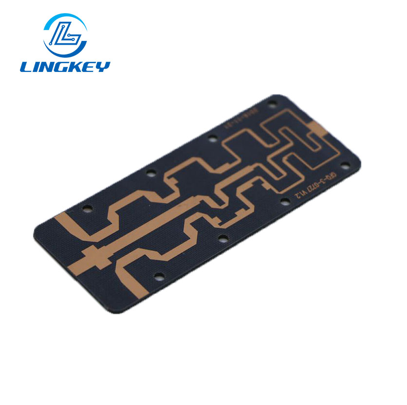
Applications of PTFE in High-Frequency, RF, and Microwave Circuit Boards
The applications of PTFE are extensive, but its true potential shines in the following areas:
- RF Applications: PTFE laminates are essential for antennas, RF signal chains, and wireless modules where low dielectric lossand signal fidelity are paramount.
- Microwave Applications: Radar and satellite communication systems use teflon PCBs due to the material’s stable dielectric constant and small dielectric loss, even at microwave frequencies.
- High-Frequency Circuit Boards: PTFE is ideal for high-speed digital designs, such as those in 5G base stations, high-frequency routers, and advanced IoT modules.
- Medical and Instrumentation: Because PTFE is chemically inert and exhibits low signal loss, it is used in critical medical imaging and diagnostic equipment.
- Military and Aerospace: PTFE circuit board substrates in missiles, satellites, and avionics ensure optimal performance in demanding, thermally variable environments.
Case Study: PTFE in 5G Telecommunications Quick Prototyping
The challenge was to create a functional 5G antenna module prototype for a top telecommunications R&D lab within less than three weeks. The company could not test a working FR4 printed circuit board (PCB) because of too much signal loss when tested at 24 GHz. The switch to a PTFE laminate allowed a design that had both low dielectric constants and a low loss tangent, giving them:
- 30% lower signal attenuation
- Reliable operation up to 260°C
- Repeatable impedance controlThe move to PTFE not only passed all consistency tests but also shortened the iteration cycle, helping the company dominate an early market window.
Quick Turn PCB Fabrication with PTFE/Teflon Circuit Boards
Production Process and Benefits
Rapid PCB manufacturing with PTFE or teflon circuit boards follows a very simplified process:
- Material Selection: Ready stock of PTFE laminates allows immediate start.
- Design for Manufacturability (DFM): Important for stackup, copper patterning and layer sequencing.
- Layer Imaging & Lamination: PTFE lamination is a specialized process, ensuring good bonding to copper without delamination.
- Precision Drilling and Routing: Advanced CNC for smooth via formation without substrate damage.
- Assembly (SMT/THT): Use of surface mount technology or through-hole components as needed.
- Functional and Electrical Testing: Makes sure that high frequency and microwave applications achieve their performance goals.
Benefits include:
- Fast prototyping for significantly shortened time-to-market.
- Early detection and remediation of design or production flaws
- Affordable prototyping for both startups and established R&D teams
- Opportunity to iterate on antenna geometries, RF layouts, and high-frequency tuning
Key Factors for Success
- Simplicity in Early Designs: Concentrate on the high priority application routes for RF in the beginning.
- Material Diversity: Select among various grades of PTFE laminate based on environmental and mechanical conditions.
- Testing and Adjustments: Stress the low dielectric loss in the high frequency and microwave circuit evaluation test plans.
- Collaboration with Experienced Manufacturers: Make sure your PCB manufacturer has the capability to work with specialty materials such as PTFE.
LingKey: Your Trusted Partner for Teflon PCB Prototyping
LingKey provides complete fast turnaround services, including high frequency circuit boards and teflon PCB. With ample knowledge of PTFE based PCB we assure you:
- Professional guidance for substrate selection and laminate stackup
- Fast prototyping, including 48–72 hour express build for urgent projects
- Tight process controls to maintain stable dielectric constant throughout
- High-level assembly for RF, microwave, and fine-pitch SMT applications.
Frequently Asked Questions
What is the dielectric constant of PTFE used in RF and microwave applications?
Does PTFE have low dielectric loss across temperature and frequency variations?
Why are PTFE PCBs more expensive than FR4 PCBs?
What modifications help overcome PTFE’s poor mechanical strength?
Is PTFE suitable for microwave and high-frequency applications beyond PCBs?
Conclusion: Why Teflon PCBs and PTFE Laminates Are Ideal for High-Frequency Applications
PTFE is special for wire work. It is rare for electronics stuff, and it helps make the best RF, microwave, and high freq chips now. It hard to work with, but Teflon PCBs and PTFE boards are the only tech that can beat what you get with FR4 PCBs in small parts and clear signals. PTFE is a tech that can make a big change how soon a new product can be in the hands of designers, engineers, and makers.
Selecting LingKey as your partner will help bring your new ideas to market faster, with established trust and the best electrical quality provided by PTFE based PCB designs.
About LingKey
LingKey is a serious shop that makes PCB and PCBA jobs for high end stuff. They do good work on high speed, high density boards that need to work at high reliability. LingKey knows how to help design engineers with RF stuff, fast builds, and high tech PCB layouts. They guide engineers through the tough parts: tricky materials, tight specs, and fast turn times from early prototypes to big runs.
")
")


")
")
")


