Semi-Flex PCB Technology : PCB Design, Semi-Flexible PCB, and Rigid-Flex PCB Solutions
Table of Contents
ToggleIntroduction to Semi-Flex PCB Technology
Part flexible PCBs are one of the great developments in the electronics world of late, closing the gap between traditional rigid boards and the fully flexible variant. With increasing demand for optimized circuit design particularly in the high-end automotive system, medical device, and consumable product, semi-flex technology has become an economical, high reliability choice. This type of PCB merges space saving flexibility with the robustness of the device, equipping the engineers with a powerful tool for their next project.
What Is a Semi-Flex PCB?
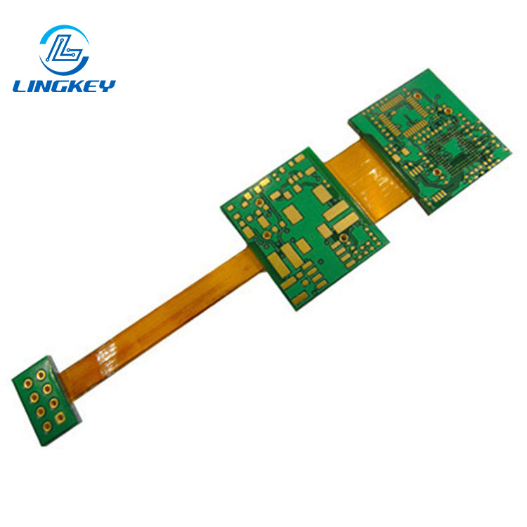
A semi-flex PCB is a specialized PCB substrate that provides the mechanical stability of rigid boards with the installation adaptability of flex pcbs – and all this without the use of any extra connecting elements or wiring harness. These PCBs merge rigid and flexible PCB segments using depth milling technique, the rigid segments are made of FR-4 material. The flexible layer, which is usually thinned to tight tolerances, enables the board to be bent during installation, but the board stays static once in use making it the perfect solution for applications that require one-time flexing.
Key benefits of semi-flex PCB:
- Eliminate the need for additional connectors and wiring.
- Achieve 3D integration in compact product enclosures.
- Reduce assembly errors by providing fewer points of failure compared to traditional rigid boards.
- Offer a cost-effective option for static applications.
The semi-rigid and semi-flexible PCBs sit between full flexible PCB and rigid PCB, they have a certain degree of flexibility. This makes semi-rigid and semi-flex PCB very useful in number of high-speed design and impedance control demanding fields like automotive, aerospace and medical applications.
Materials and Core Structure
The core of the semi-flex PCB is the proven rigid FR-4 for the rigid parts, with localized depth milling forming flexible areas. A minimum bend radius of 6x thickness of the flex layer is generally recommended for long life—therefore with a flex thickness of 0.3mm you should maintain a bending radius of approximately 1.8mm.
Core Materials and Build:
- FR-4 glass-reinforced epoxyfor both rigid and flex zones
- Copper foil(1/2 to 2 oz) for circuit traces
- Solder maskand surface finish options such as ENIG, HASL, or OSP
- The depth-milled area provides for controlled flexing. The rigid portion serves to mechanically support a populated component.
Feature | Rigid Section | Semi-Flex Section |
Material | Full-thickness FR-4 | Depth-milled FR-4 |
Thickness (typically) | 1.6mm | 0.2–0.4mm |
Minimum Bend Radius | N/A | 6x thickness of the flex |
Load Tolerance | High | Moderate |
Repeated Flexing | N/A | Not intended |
By combining rigid and flexible sections, semi-flex PCBs provide strength and flexibility on one board.
Manufacturing Process of Semi-Flex PCBs
Making a semi‐flex PCB includes multiple accuracy demanding steps which now can be realized by the application of modern PCB manufacturing technology. Additional milling operations are needed to create the flexible areas as compared to normal rigid panels.
- Material Preparation:Choice of the high-quality FR-4, copper foil, and lamination stack-up.
- Circuit Imaging and Etching:Imaging followed by chemical etching PCB traces in copper layers.
- Lamination:The layer pressing produces a homogeneous multilayer panel or double/single-sided composite.
- Drilling and Plating:Mechanical drilling, through hole plating and via formation for signal interconnection.
- Depth Milling:CNC equipment mills selected regions to reduce thickness, enabling flex.
- Surface Finish:Applying ENIG or HASL to protect copper and optimize soldering.
- Solder Mask Application:Insulation and protection.
- Final Testing and Panelization:AOI, flying probe and x-ray inspection to guarantee the integrity and high reliability.
With the combination of rigid parts and the flex parts through the use of standard design and manufacturing processes, the rigid-flex PCB can be produced in large quantities for stable performance in semi flex PCBs.
Common Semi-Flex Technologies
Two main manufacturing approaches are used for semi-flex PCB design:
- Depth-Milled FR-4:Most frequent. The region that must flex is CNC-milled to a depth—suitable for strong 3D embedding in control units in automotive and consumer electronics.
- Thin-Core Semi-Flex:Is a uniformly thinner FR-4 laminate, which enables bending on board at lower levels of mechanical stress. Used in applications where the forming is simplified, but reduced ruggedness is acceptable.
Selecting the best option depends on your individual requirements for bend radius, flex cycle, and assembly complexity.
Key Characteristics and Specifications
A semi-flex PCB offers a good compromise between flexibility and rigidity, allowing parts placement on both sides and flexing only during installation. Some notable specs:
- Material:Standard FR-4 for strength and cost-effectiveness.
- Thickness of the flexible layer:2mm–0.4mm (varies by design).
- Minimum bend radius:6x thicker minimum—critical in the early design to protect performance.
- Impedance control:Practicable for a high-speed design; 50 Ohms for multiple signal lines can be implemented even in pocketed areas, this is important for RF and high-speed digital signals.
- Surface finish options:ENIG for high reliability in harsh environments, HASL for general electronics.
- Layer count:Commonly 2-4 layers for semi-flex, but can go higher.
- Consistent electrical insulation and mechanical strengthin flexible areas.
Comparing with Rigid, Flexible, and Rigid-Flex PCBs
Semi-flex PCBs bring together the best aspects of rigid and flex PCBs, delivering reduced requirement for additional connectors as compared to using only the rigid boards:
Feature | Semi-Flex PCB | Rigid PCB (Traditional) | Flexible PCB | Rigid-Flex PCB |
Flexibility | Static (install) | None | Dynamic | Static/Dynamic |
Need for additional connectors | No | Yes | No | No |
Durability | High | High | Lower | High |
Space Saving | Excellent | Limited | Excellent | Excellent |
Assembly Complexity | Medium | Low | High | High |
Cost | Moderate | Low | High | Very high |
3D Integration | Good | None | Excellent | Excellent |
Impedance Control | Achievable | Easy | More complex | Complex |
Semi-flex PCBs provide the ideal compromise for use cases where rigid boards are excessively large and flex PCBs are too complex or simply not required.
Advantages and Limitations
Key Benefits of Semi-Flex PCB
- Space efficiency:The PCBs of your next project can be smaller, allowing for 3D stacking in compact product housings.
- Cost-effective:Semi-flex PCBs are a more cost-effective option over full flexible or rigid-flex for one time bending.
- Assembly simplification:Eliminate the need for additional connectors, reducing cost and points of failure.
- High reliability:By integrating rigid and flexible regions, these boards improve the durability of the device in static bend scenarios.
- Optimized circuit design:Allow design flexibility with the high-speed, impedance-controlled signal performance.
Limitations
- Not for dynamic flexing:Use cases with constant bending or folding require full flex PCBs.
- Bend radius limits:Usually, the minimum bending radius is 6 times the thickness of the flexible section for safety concerns.
Applications of Semi-Flex PCBs
Semi-flex PCBs is a combination of flexibility and rigidity, which can be used in many fields of industries.The semi-flex PCBs applications are:
Automotive Systems
Semi-flex PCBs are widely utilized in vehicle control units, dashboard modules and lighting systems. The formability enables seamless integration in complex automotive enclosures for high reliability and reduction of connectors—vital to the reduction of potential sources of failure, and enabling of 3D integration.
Consumer Electronics
From foldable smartphones to wearables and laptop hinges, semi-flex PCBs are enabling thinner and lighter form factors. PCBs use rigid sections for components and flexible sections for running, accommodating the trend of miniaturization in modern electronics.
Medical Devices
Medical electronics require ruggedness and small size. Semi-flex PCBs are utilized in imaging equipment, portable monitors and implantable diagnostic devices, providing optimized circuit design and high reliability in applications where patient safety is critical.
Industrial Automation & Equipment
Sensors, HMI panels, and rugged control boards in industrial applications utilize semi-flex designs to pack electronics into non-uniform enclosures, offering strength and removing the need for extra wiring.
Aerospace Technology
The simplicity of assembly and the risk of in-flight failure is being minimized for semi-flex solutions used in aircraft modules and satellite systems, that take advantage of the weight and space savings, and with a reduced chance of in-the-flight failure.
Designing and Installing Semi-Flex PCBs
Good semi-flex PCB design is part art, part engineering, and part sticking to the tight design envelope.Here’s what to consider for design and installation:
Design Practices
- Specify the areas to be bent in the beginning using your CAD software, improper definition can lead to loss of integrity.
- Hold the minimum bend radius to 6 x thickness of the flex layer in the depth-milled area. For example, if the thickness of your flexible section is 0.3mm, your radius of bend must be at least 1.8mm.
- Route traces perpendicular to the bend for maximum life.
- Avoid putting components in flexible zones.
- For impedance control, important for high-speed design, make sure stack-up and trace sizes are appropriate for the signals. Most semi-flex boards are designed to 50 Ohms for many signal traces.
Installation Practices
- Bend once only during assembly. Rigid-flex boards Semi-rigid PCBs applications Semi-flex may be bent, but unlike rigid or true flex PCBs, it is not made for repetitive motion.
- Do not sharply crease the flex zone; always use gradual, smooth curves.
- Use proper fixturing and handling to avoid over-bending or misalignment.
Fewer Points of Failure
Instead of using traditional rigid boards with connectors and ribbon cables, semi-flex PCBs enable the system to be integrated directly, minimizing the number of potential faults and simplifying the PCB assembly.
Semi Rigid-Flex PCB Technology
Semi rigid-flex technology is blurring the distinction between semi-flex and flex circuit. With rigid and flexible PCB components combined, these high-performance circuit boards are perfect for extremely compact systems that need 3D integration as well as a small amount of flexibility. Semi rigid-flex are good when parts of the board is exposed to intermittent dynamic stress, providing a balance between cost and complexity when compared with conventional rigid and rigid-flex boards.
Quality Assurance and Testing
The high reliability of semi-flex PCB production is based on strong design and process control.
- Automated Optical Inspection (AOI):Detects micro-defects, especially around depth-milled regions.
- Flying Probe Testing and X-Ray:Checks connection and inspects inner layers—necessary for multi-layer semi-flex circuits.
- Mechanical Bending Tests:Verify the bend radius and flexible layer strength are within specifications after PCB fabrication.
- Impedance Testing:Where required, checks that the impedance control is still within specification after
Troubleshooting & Performance Factors
Several performance factors must be continually monitored and optimized:
- Signal Integrity:Stack-up and layout are important for high-speed lines. Proper material and geometry are used to maintain 50-Ohm impedance where required.
- Solder Mask and Copper Weight:Secret to Mechanical Strength—excess copper or lack of solder mask will cause micro-cracking on flexure areas.
- Thermal Management:Solid sections also conduct heat better, so you should keep sensitive components and high power circuits on these areas.
- Inspection:Routine AOI, X-ray and flying probe testing detect problems early allowing for minimal cost in rework.
FAQ: Semi-Flex PCB Technology
What is the main advantage of using semi-flex PCBs compared to traditional rigid boards?
Can semi-flex PCB technology be used for all types of PCB projects?
What should be the minimum bend radius of 6 times thickness in the flexible section?
How do you achieve impedance control in semi-flex designs?
Conclusion
Semi-flex PCBs give today’s product designers the ability to adopt new design layouts over traditional rigid layouts. Benefiting from cost-effective manufacturing, enhanced reliability, 3D circuit integration, and ease of assembly, these PCBs form a unique combination of the rigid and flexible technology applicable to a broad spectrum of industries.
The combination of rigid and flexible PCB features allows you to optimize both performance and cost, minimize the use of connectors, save space and provide high reliability across automotive systems, medical devices, industrial control and consumer products.
With the stackup design, controlled depth milling and early manufacturability reviews, the semi-flex PCB can produce a solid performance in automotive, medical, industrial and consumer applications. LingKey enables this with engineer-led DFM review, precision fabrication and application-driven validation—helping teams go from concept to production with confidence.
")
")


")
")
")


