What is a Breakout Board? Breakout Board Basics
Table of Contents
ToggleIntroduction to Breakout Boards
If you’ve spent any time reading electronics forums or project guides, you may have stumbled upon the term breakout board — and if that’s the case, you’ve already been introduced to one of the best hackaday solutions in circuit prototyping. Breakout boards allow easy handling and experimentation with small or complex electrical parts (like SMD parts and ICs, integrated circuits) by converting them to a higher form factor. This enables the use of a solderless breadboard for prototyping, which brings cost and build time down even further for early designs.
Definition and Function of a Breakout Board
A breakout board is an essential aspect of circuit design – that is, a tiny printed circuit board that makes the pins of an IC or other electrical component easy to reach out to. A lot of breakout boards come with a pin header that has the standard 0.1 inch spacing making it compatible with breadboards, dip packages or sockets. What makes a breakout board special is that it converts SMD only parts that cannot be placed into a breadboard, so you can quickly add onto your microcontroller dev board or custom PCB.
If you want to know how to use a complex module (like an xyz breakout board for a specialized sensor or wireless chip) for your newest Arduino project just take the one that has good documentation and is well labeled. These boards also have voltage supply pins (commonly referred to as VCC or 3.3v or 5v) and act as an interface between SMD chips and the larger, DIP components.
Uses and Applications of Breakout Boards
Breakout boards power everything, from high school science projects to professional prototypes. Here are they are used for common purposes:
- Integrating SMD chips into prototypes:Most SMD sensors and modules are inaccessible without a breakout.
- Testing and validating ICs:Engineers can breadboard any IC and with the datasheet test pin functionality on-the-fly.
- Connecting to popular platforms:You can also get advanced comms or sensor modules to use with your Arduino or Raspberry Pi. Just connect the breakout to your Arduino based on the labelled pins.
- Expanding breadboard capabilities:With breakout boards, you can work with both DIP and SMD modules on a breadboard, thus facilitate a wide range of prototypes.
Some breakout boards sold as kits or bundled with other products will also come with the headers, documentation, and sample code for a breakout board, making quick prototyping easy.
Why Use a Breakout Board?
Space Efficient Prototyping
Breakout boards really come in handy when SMD parts don’t come in large DIP package variants. Breakout Boards are meant to be used when you need a larger form factor to make tiny electronic components usable on a breadboard.
Designed for Reuse
Unlike ICs mounted on a custom PCB, breakout boards are often designed to be reused. You can transfer them from one job to another, treat them as educational tools and dongles for a quick development.
Clear Pin Labeling and Simplified Interfacing
Your breakout board should be well-labeled with VCC, GND, and I/O on each pin to help avoid accidental wiring errors. They generally break every pin out to a header, so you can wire up complex circuits without guessing or flipping through obscure datasheets for the names of the integrated pins.
DIP Versions May Not Be Available
In recent years, newer devices are often available only in SMD form. Breakout boards are SMD adapters that allow you to use high-tech hardware on traditional breadboard configurations, letting you utilize technology that is not otherwise accessible for hand prototyping.
Main Features and Specifications
When selecting a breakout board, calculate on the ground of the specs on either the breakout board or datasheet. The most applicable information is:
Feature | Description |
Pin Spacing | 0.1 inch (2.54mm) for standard breadboards |
Voltage Supply Pin | Look for clearly marked VCC or supply voltage pins |
Supply Voltage | Most boards work at 3.3V, 5V, or both (Arduino has two voltage) |
Good Documentation | Essential for wiring, code, and troubleshooting |
Mounting Options | Holes or headers for breadboards, perfboards, or custom PCBs |
Compatibility | With Arduino, Raspberry Pi, and other microcontrollers |
Common Types of Breakout Boards
Common breakout boards for almost every application are available.Here are1 the most popular categories:
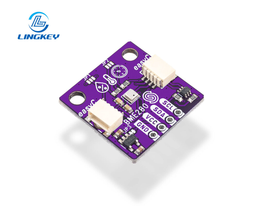
Sensor Breakout Boards
Temperature sensors, accelerometers, gyroscopes, and light sensors in xyz breakout board configurations.
- Example:BMP280 (pressure/temperature), MPU-6050 (accelerometer/gyroscope).
Communication Modules
Bluetooth modules, Wi-Fi modules, and GPS modules. Many breakout boards reference standard protocols, allowing you to interface with your microcontroller or PC easily.
Power Regulators and Interface Boards
Voltage regulators, level shifters, USB-to-serial adaptors, etc are essential when converting voltages or interfacing to new logic standards. A level shifter breakout makes for a safe 3.3V <-> 5V connection.
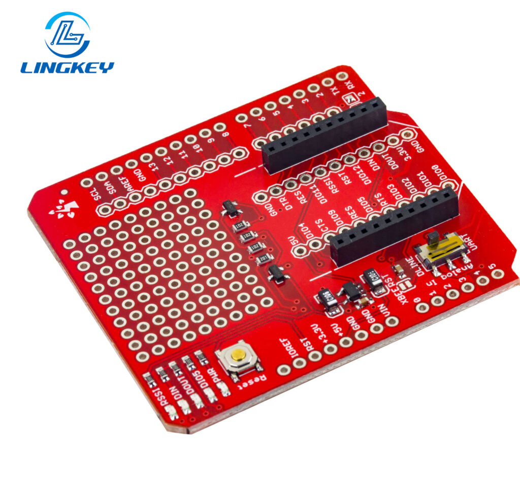
Microcontroller Breakout Boards
A microcontroller development board such as Arduino Nano, ESP8266/ESP32 DevKit or Raspberry Pi Pico is EMPTY on all pins in a breakout manner.
Benefits of Using a Breakout Board
- Space Saving:Make compact SMD devices DIP-width for breadboard use (they are bulkier, but easier to handle).
- Reusability:Move between projects without resoldering.
- Clear Pin Labeling:Keep wiring straightforward, even when using many breakout boards.
- Faster Debugging:Quickly identify and resolve issues with clearly marked pins.
- Good documentation:Vendors such as SparkFun and Adafruit offer excellent support, examples and code for a breakout board use case.
- Flexible Voltage:Often handle both common voltage options; for Arduino, has two: one at 3.3 volts, one at 5 volts.
Key Considerations When Selecting a Breakout Board
Before you find a breakout board for your application, some essential considerations are:
- Specs on the breakout board:Always check the specs! Ensure you know maximum safe voltage, pinout, current rating, and logic compatibility.
- Pinout and Size:Must match your breadboard or project needs.
- Documentation:Good documentation speeds up learning and debugging.
- Soldering Requirements:Some are pre-soldered; others are sold as kits for custom pin arrangements.
- Compatibility:Confirm with your microcontroller development board (e.g., Arduino, ESP32) and intended platform.
Tips for Getting Started with Breakout Boards
- Look is in the Arduino IDE:Most breakout boards have example libraries that you can simply utilize and modify and the Arduino IDE includes good support for common sensor and communication modules.
- Double-check the supply voltage:Before hooking anything up, make sure your breakout board voltage is the same as your microcontroller (Arduino comes in two voltage supply flavors: 3.3 volts and 5 volts). Applying 5V to a 3.3V only board will start to magic smoke from VCC or voltage supply pins clearly labeled, Look for. Some breakout boards are dual-voltage, but always double-check the specs.
- Read the Documentation:The breakout boards from good manufacturers come with good documentation. This will have wiring diagrams, sample code for a breakout board, and hardware requirements. Such resources can also help you figure out how to use each board properly.
- Start Simple:Try a generic breakout board (eg light or temperature sensor) first. Use a tasteless breadboard for prototyping — this reduces risk and lets you swap out components fast.
- Adjust the Codeas Needed: Many breakout boards refer to open source Arduino After you have your board wired up, you might need to modify the code in the Arduino IDE for your particular setup – for example if you want to change the pin assignments, or the values for supply voltages.
- Double-Check Connections:Make sure all pins are labeled, on both the device and the cable (esp. power, ground, and data lines), before you plug anything in. One easy check: the breakout board you’re using has corresponding signal references in its labeling and the example code.
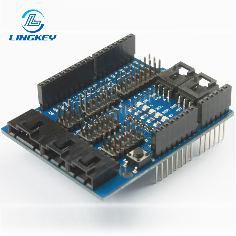
Breakout Boards vs. Arduino Shields
You may wonder why you’d choose a breakout board—i.e., a modular pin-adapter for an individual component—over an Arduino shield.
- Arduino Shieldsstack directly on the main board, quickly expanding functionality for beginners.
- Breakout Boards offer more versatility, are compatible with any microcontroller development board, and enable more modular, space-efficient, and recyclable designs.
One important difference is that Arduino shields often fit only Arduino boards and are sometimes even larger both horizontally and vertically. Breakout boards work across platforms, can be reused, and have better support for custom configurations or for when you need a lot of breakout boards in one system.
How to Use a Breakout Board: Step-by-Step Guide
Gather Components
- Your breakout board(s)
- Microcontroller (Arduino, Raspberry Pi, etc.)
- Jumper wires
- Solderless breadboard
- USB cable/power supply as needed
Consult Documentation
- Download the datasheet or manual for your breakout board.
- Check the specs—verify if your board requires supply voltage around 3.3 volts or 5 volts.
Insert into Breadboard
- Seat your breakout board so each header pin is accessible for wiring.
- Many boards are designed to fit DIP packages, aligning with the breadboard slots.
Wire to Microcontrolle
- Connect VCC/voltage supply pin, GND, and any data pins (such as SDA/SCL for I2C, TX/RX for UART).
- Use the provided documentation and sample code for a breakout board to confirm connections.
Power Up
- Attach your microcontroller’s USB or other power source.
- Double-check that all voltage supply pins are correctly wired.
Upload & Run Code
- Open example code in Arduino IDE.
- Adjust the code for your specific setup as necessary (such as defining which pins are used or selecting correct voltage).
- Upload code to the microcontroller and observe output.
Troubleshooting Common Issues
- No Signal/No Response:Make sure everything is wired up correctly, especially the VCC and GND lines. Many breakout boards have only one supply voltage pin—g. VCC—which can be configured for either 3.3V or 5V.
- Voltage Mismatch or Instability:Make sure your supply voltage matches the soak-up board requirements. There are two main supply voltages in Arduino, so choose the one that suits your needs.
- Incorrect Data/Behavior:Verify wiring with documentation. Sensors and modules that use I2C or SPI may need pull-up resistors (hardware) or the correct initialization (software) if used on a breakout board.
- Board Gets Hot:Unplug right away! Maybe you used the wrong supply voltage, or there’s a short.
Related Products and Accessories
To maximize your experience, consider these supporting items:
- Jumper wiresfor flexible connections
- Solderless breadboardsfor rapid prototyping
- Kits sold as bundlesof common breakout boards
- Level shiftersif working with mixed voltages
- USB-to-serial adaptersfor programming or debugging
- Comprehensive toolkits(soldering supplies, wire strippers) for more advanced work
Frequently Asked Questions about Breakout Boards
What should I check before using a new breakout board?
Can I use many breakout boards at once?
Where do I find a breakout board for a specific chip or sensor?
Can I use a breakout board with a solderless breadboard?
How do I know which voltage supply to use?
Conclusion: The Importance of Breakout Boards
Breakout boards are an essential interface for bringing modern SMD components into the realm of usable circuits. They allow quicker evaluation, easier debugging and more reliable early stage validation by exposing otherwise hidden pins and providing standardised interfaces to breadboards and test equipment. In educational settings and professional engineering workflows, breakout boards simplify constraints and allow design engineers to focus on bringing up functionality, as opposed to working around packaging constraints.
In professional pcb design, breakout boards are commonly utilised in the context of structured prototyping and verification. At LingKey, they are often utilized for needs such as pre-layout testing, interface validation, and functionality testing prior to committing designs to custom pcb fabrication. This allows potential electrical or compatibility issues to be discovered earlier in the process, resulting in better design confidence and less expensive iterations in late-stage production.
For electronics trending towards higher integration with shorter development cycles, breakout boards are still a viable item to have available. When combined with good design practices and knowledgeable manufacturing support, they are still an effective means of converting ideas to robust, producible electronic systems.
")
")


")
")
")


