Difference Between SMT and SMD Explained
Introduction
In electronics, two buzzwords you’ll find at the heart of modern electronics are SMT (Surface Mount Technology) and SMD (Surface Mount Device). They’re essential in the construction of today’s high-performance miniaturized devices, and form the substrates of every modern printed circuit board (PCB). But the two are often confused by designers, engineers, and purchasers alike.
If you want to design reliable, small, or high-speed products – or collaborate with top PCB assembly services to realize your ideas – you need to understand SMT and SMDs.
As a high quality PCB manufacturer and PCBA assembly supplier, LingKey provides high precision SMT mounting, reflow solderering, SPI/AOI/X-Ray inspection and function testing. Our robotic SMT lines are designed for both prototyping and volume production to provide consistent quality and reliability for your long term projects.
What is SMT (Surface Mount Technology)?
History and Evolution of SMT
SMT is the name of the process where electronic components are mounted directly onto the surface of a printed circuit board instead of passing component leads through holes like in through-hole technology. SMT makes it possible for electronics to be much smaller and lighter, enabling them to evolve from bulky desktop machines into wearable, portable gadgets.
Developed in the late 20th century, the SMT technology substituted through-hole technology by introduction of high-speed automated PCB assembly lines. It has long since become the standard for the electronics industry for everything from integrated circuits (ICs) to resistors and capacitors.
SMT Assembly Process
The SMT manufacturing process is a streamlined, precise, and highly automated flow:
1.Stencil Printing (Solder Paste Application): Solder paste (a mixture of powdered solder and flux) is applied to the PCB pads through a fine stencil. This is important to be able to have strong and dependable electrical, mechanical connection.
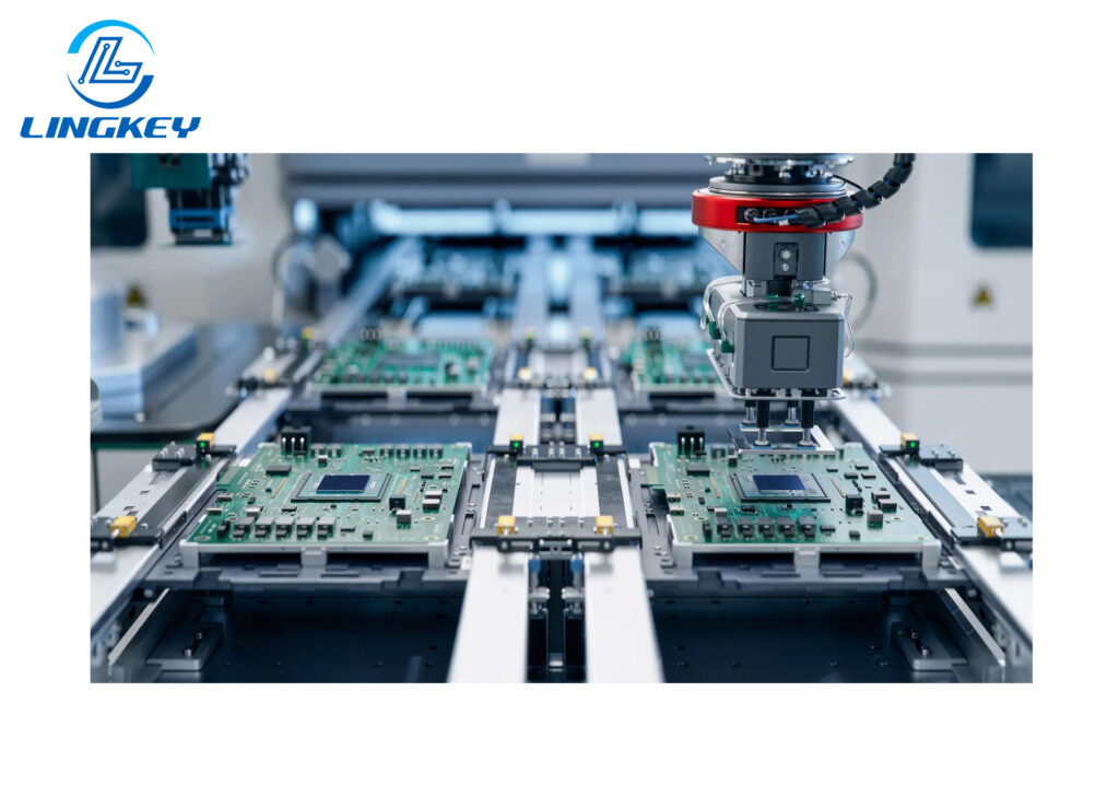
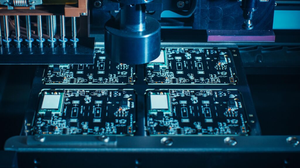
2.Component Placement: Using the pick and place SMT machine, SMT chip components are placed on the PCB. Robotic systems can place components at mind blowing speeds, each one being placed directly on the surface of the PCB.
3.Reflow Soldering: Boards are run through a reflow oven, where the solder paste is heated to a liquid state and the components are soldered directly to the PCB. The right profiles for various temperatures during reflow also guarantee that even the most delicate integrated circuits are safely mounted.
4.Automated Optical Inspection (AOI): High-resolution cameras inspect for missing components, misalignment, or solder bridges, ensuring quality when the boards are moving forward in the SMT process.
5.Functional Testing: Each and every smt pcb is subjected to electrical testing to verify that all circuits function as intended.
SMT Features and Advantages
The benefits of surface mount technology are visible at every stage of the electronics product lifecycle:
- Higher Component Density:SMT enables the packing of thousands of surface mount components into a small area, making the best use of the PCB real estate. Improved Electrical Performance: Shorter electrical paths mean improved electrical performance due to shorter traces, minimizing signal delay and losses.
- Faster Automated PCB Assembly:SMT equipment automates placement and soldering, reducing labor costs and human error.
- Cost-Effective Manufacturing:High-speed processes and less manual handling lower total costs.
- Size and Weight Reduction:As components are mounted directly onto the surface, products can be smaller and lighter—a critical advantage in mobile and wearable electronics.
- Environmental Benefits: Less waste, less energy used, and compliance with strict global standards.
What is SMD (Surface Mount Device)?
What Are SMD Components?
SMD technology is about the physical electronic components that are meant to be used with SMT. SMD electronic components do not have long wire leads instead, they have metalized ends or pins which are soldered directly onto the surface of a PCB.
These parts—such as resistors and capacitors, ICs and sensors—are far smaller than their conventional through-hole equivalents and are essential for creating small, battery powered electronics.
Types of SMD Components
SMD components come in three main categories:
Passive Components
- Resistors and Capacitors:Store and release electrical energy, control voltage, or filter signal noise.
- Inductors:Used in filtering, energy storage, and voltage regulation.
Discrete Components
- Diodes, LEDs, Transistors:Manage current flow, switch signals, or provide illumination (SMD LEDs).
Electromechanical Devices
- Connectors, Switches, Relays:Interface with the outside world, route signals, or trigger circuits.
SMD Type | Function | Typical Size | Industry Use |
Chip Resistor (0402, 0603) | Control/divide current, voltage | 1.0×0.5 mm | Consumer, Industry |
Ceramic Capacitor | Store/release energy, filter noise | 1.6×0.8 mm | Telecom, Energy |
SOT-23, SOD-123 | Diodes, transistors, small ICs | 2.9×1.3 mm | Signal/control circuits |
QFN/BGA | Integrated circuits, MCUs, FPGAs | Varies (small, dense) | High-speed, RF, mobile |
SMD Sensors/LEDs | Measurement, display | Ultra-compact | Medical, IoT, Display |
SMD Features, Advantages, and Challenges
Features and Benefits
- Miniaturization:Smaller size and weight compared to traditional through-hole components, allowing thinner devices.
- High-Frequency Performance:Shorter leads improve signal integrity—vital for wireless, RF, and fast data circuits.
- Mechanically Robust: Mounted directly onto the PCB—they handle vibration and shock better, reducing failures in automotive or aerospace designs.
Challenges in SMD Technology
- Assembly Handling:Tiny sizes make manual prototyping or repair challenging; automation preferred.
- Thermal Management:High-density SMDs may require vias or special layouts to deal with heat from hot-running integrated circuits.
- Package Identification: Small size can limit on-chip markings, making part traceability and orientation critical during assembly.
Common Packaging and Marking
Package Type | Typical Component Examples | Dimensions (mm) | Marking Style |
0402 | Resistors, capacitors | 1.0 x 0.5 | Minimal (numbers or dots) |
0603 | Resistors, capacitors | 1.6 x 0.8 | Numeric code/value |
SOT-23 | Diodes, transistors | 2.9 x 1.3 | Letter/number code |
QFN/BGA | Microcontrollers, ICs | Various | No visible, tray-labeled |
PLCC | EEPROMs, logic ICs | Varies | Label on package |
SMD Sensor | Temperature, motion, etc. | Ultra-compact | Model/lot on reel |
Quality and Industry Standards
- IPC Standards:Ensure soldering consistency and reliability in SMT production, essential when placing hundreds of tiny components directly onto the PCB.
- JEDEC Standards:Define package outlines for SMDs, supporting easy pick-and-place and consistency in pcb manufacturing and assembly services.
- RoHS and REACH:Environmental directives influence material selection in both SMT processes and SMD technology.
SMT vs. SMD: Key Differences
Knowing the difference between SMT and SMD will allow you to prevent expensive errors in design and manufacturing.
Conceptual and Functional Comparison
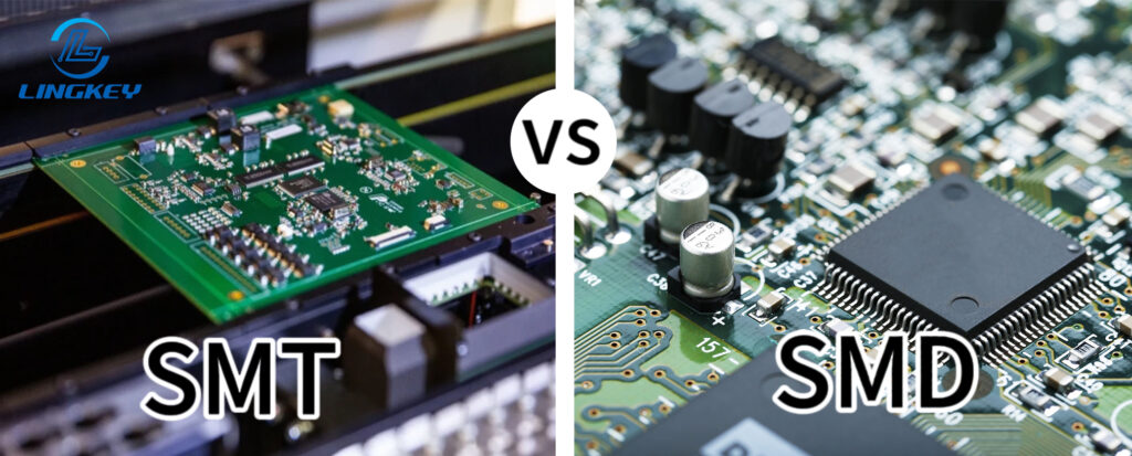
- SMT is the process of production where electronic components are mounted or placed directly onto the surface of PCB, which makes placement easier and soldering faster than through-hole assembly.
- SMDdescribes the electronic components designed for that process—miniature devices that are soldered directly onto and mounted directly onto the surface of a printed circuit board.
Application Comparison
- SMT technology is chosen for projects needing higher component density, compact PCBs, and automated PCB assembly. It’s ideal for batch manufacturing or whenever small size, speed, or cost are priorities.
- SMDs are needed when designing contemporary designs – because they allow components to be placed on the surface of the circuit board, instead of being limited to through-hole space, which results in the development of new, miniaturized products.
- Through-hole components still find a place in designs where mechanical strength, manual prototyping, or high voltage isolation are vital.
SMT vs SMD vs THT Comparison Table
Feature | SMT | SMD | THT (Through-Hole) |
What is it? | PCB assembly process | Electronic component | Classic assembly process |
Key Advantage | High speed, higher component density, reduced size/weight | Miniaturization, improved electrical performance, easy pick/place | Strong mounting, power/ruggedness |
Placement style | Components directly onto surface | Designed for PCB surface mounting | Leads inserted into PCB holes |
Size / Weight | Small, lightweight assemblies | Ultra-compact, light components | Larger, heavier assemblies |
Automation | Fully automated | Yes—supports automated assembly | Manual or semi-automated |
Example use | Smartphones, tablets, IoT, automotive | Nearly all modern electronics | Power, connectors, mechanical stress |
Electrical performance due to shorter paths | Excellent | Excellent | Moderate due to long lead lengths |
Repairability | Needs special tools (hot air, rework) | Difficult for smallest packages | Easy, especially for prototyping |
SMT and SMDs in PCB Manufacturing
With the miniaturization of electronics and increasing requirement, the synergy of SMT and SMD technology has changed the definition of pcb fabrication and assembly services.
At LingKey, our lines for SMT production are capable of:
- 01005 micro-components
- QFN, BGA, CSP, LGA and other high level packages
- Double-sided reflow
- Automated cleaning of stencil
- SPI, AOI, and X-Ray full inspection
Make Sure that Every PCBA passes the high standard of quality and reliability.
From Prototype to Mass Production
- PCB Prototype Stage:SMDs can be hand-placed and reflowed for proof-of-concept. SMT involves careful stencil printing and hands-on soldering for testing circuit board design.
- SMT Production Scale:Automated pcb assembly services use advanced SMT equipment for high-throughput, minimizing human error and boosting yields.
- Hybrid Designs:While mostly surface mount, critical connectors or transformers may use through-hole components for added strength or heat dissipation.
Applications in the Electronics Industry
Industry Examples
- Wearables & Smartphones:SMT pcb designs with SMD sensors, antennas, and ICs enable unprecedented versatility and miniaturization.
- Automotive & Industrial Automation:Vibration-resistant, thermally-robust surface mount components ensure durable, safe systems.
- Medical & High-Reliability:Dense circuit layouts using SMD technology power compact hearing aids, implantables, and remote patient monitoring devices.
- High-Speed Networks & Datacenters:Improved electrical performance due to shorter traces and lower inductance is a must for routers and servers.
Designing for Harsh Environments
- Thermal Performance:SMDs, placed correctly, dissipate heat much more efficiently, which is vital in power applications and RF electronics.
- High-Vibration/Mechanical Stress: SMT components resist shock due to compact size, remaining reliable through years of automotive or industrial use.
FAQ: SMT vs. SMD
Are they interchangeable terms?
Can you mix SMDs with traditional through-hole components on a PCB?
What factors should guide selection of SMD vs. through-hole components?
Why is improved electrical performance due to shorter signal paths so important?
Conclusion: Miniaturization, Cost-Efficiency & Reliability
SMT is the technology of the PCB assembly in which electronic components are mounted on the surface of the board, and SMD is the type of components which can be used in this assembly process. That differentiation is critical to maintaining reliability, minimizing cost, and providing the miniaturization required for contemporary products.
SMT and SMD are essential components of today’s electronics, allowing for the manufacturing of smarter phones and IoT devices and more capable medical, automotive, and high-speed network systems. Understanding their differences and best practices enable next generation printed circuit design, cost savings, and improved product performance.
As a PCB Manufacturer, LingKey electronics also offers in-house turn-key solutions: PCBA – With one-stop services including PCB fabrication, component sourcing, SMT assembly, reflow profiling, AOI/X-Ray inspection and functional testing, LingKey is your trusted partner for PCBA assembly and manufacturing. From prototype to high-volume production, LingKey guarantees that every board meets the highest levels of stability, performance and consistency.


